Polar coordinate system (polar coordinates)
A polar coordinate system on a plane is a combination of a point O, called a pole, and a half-line OX, called the polar axis. In addition, it is specified scale segment for measuring distances from points of the plane to the pole. As a rule, a vector \vec(i) is selected on the polar axis, applied to point O, the length of which is taken as the value of the scale segment, and the direction of the vector specifies the positive direction on the polar axis (Fig. 2.28a).
The position of point M in the polar coordinate system is determined by the distance r ( polar radius) from point M to the pole (i.e. r=\vert\overrightarrow(OM)\vert) and the angle \varphi (polar angle) between the polar axis and the vector \overrightarrow(OM). The polar radius and polar angle are polar coordinates points M, which is written as M(r,\varphi) . The polar angle is measured in radians and measured from the polar axis:
In the positive direction (counterclockwise), if the angle value is positive;
In the negative direction (clockwise direction) if the angle value is negative.
The polar radius is defined for any point in the plane and takes non-negative values r\geqslant0 . The polar angle \varphi is defined for any point in the plane, with the exception of the pole O, and takes the values -\pi<\varphi\leqslant\pi , called main values of the polar angle. In some cases, it is advisable to assume that the polar angle is defined up to the terms 2\pi n , where n\in\mathbb(Z) . In this case, the values \varphi+2\pi n of the polar angle for all n\in\mathbb(Z) correspond to the same direction of the radius vector.
The polar coordinate system Or\varphi can be associated with a rectangular coordinate system O\vec(i)\vec(j), the origin O of which coincides with the pole, and the abscissa axis (more precisely, the positive semi-abscissa axis) coincides with the polar axis. The ordinate axis is completed perpendicular to the abscissa axis so that a right-handed rectangular coordinate system is obtained (Fig. 2.28, b). The lengths of the basis vectors are determined by the scale segment on the polar axis.
On the contrary, if a right-handed rectangular coordinate system is given on the plane, then, taking the positive semi-axis of the abscissa as the polar axis, we obtain a polar coordinate system (associated with the given rectangular one).
Let us derive formulas connecting the rectangular coordinates x,y of a point M, different from the point O, and its polar coordinates r,\varphi. According to Fig. 2.28,b we get
\begin(cases)x=r\cdot\cos\varphi,\\y=r\cdot\sin\varphi.\end(cases)
These formulas allow you to find rectangular coordinates from known polar coordinates. The reverse transition is performed according to the formulas:
\left\(\begin(aligned)r&= \sqrt(x^2+y^2),\\ \cos\varphi&= \frac(x)(r)=\frac(x)(\sqrt(x^ 2+y^2)),\\ \sin\varphi&= \frac(y)(r)=\frac(y)(\sqrt(x^2+y^2)).\end(aligned)\right .
The last two equalities determine the polar angle up to terms 2\pi n , where n\in\mathbb(Z) . For x\ne0 it follows from them that \operatorname(tg)\frac(y)(x)\varphi~(-\pi<\varphi\leqslant\pi) is found according to the formulas (Fig. 2.29):
\varphi=\left\(\begin(aligned)\operatorname(arctg)\frac(y)(x),\quad&x>0,\\\pi+\operatorname(arctg)\frac(y)(x),\ quad&x<0,\,y\geqslant0,\\-\pi+\operatorname{arctg}\frac{y}{x},\quad&x<0,\,y<0,\\\frac{\pi}{2},\quad&x=0,\,y>0,\\-\frac(\pi)(2),\quad&x=0,\,y<0.\end{aligned}\right.
Example 2.9. In the polar coordinate system Or\varphi :
a) draw coordinate lines r=1,~r=2,~r=3,~\varphi=\frac(\pi)(4),~\varphi=\frac(\pi)(2);
b) depict points M_1,~M_2 with polar coordinates r_1=3,~\varphi_1=\frac(9\pi)(4),~r_2=3,~\varphi=-\frac(7\pi)(4). Find the principal values of the polar angles of these points;
c) find the rectangular coordinates of the points M_1,~M_2.
Solution. a) The coordinate lines r=1,~r=2,~r=3 represent circles of corresponding radii, and the lines \varphi=\frac(\pi)(4), \varphi=\frac(\pi)(2) And \varphi=\frac(3\pi)(4)- semi-straight (Fig. 2.30, a).
b) Let's plot the points M_1\!\left(3,\frac(9\pi)(4)\right) And M_2\!\left(3,-\frac(7\pi)(4)\right)(Fig. 2.30, b, c). Their coordinates differ in polar angle, however, they have the same main meaning \varphi=\frac(\pi)(4). Therefore, this is the same point, which coincides with the point M\!\left(3,\frac(\pi)(4)\right), shown in Fig. 2.30, a.
c) Taking into account point “b”, let’s find the rectangular coordinates of point M. Using formulas (2.17) we obtain:
x=r\cdot\cos\varphi=3\cdot\cos\frac(\pi)(4)=\frac(3\sqrt(2))(2);~y=r\cdot\sin\frac( \pi)(4)=\frac(3\sqrt(2))(2), that is M\!\left(\frac(3\sqrt(2))(2),\frac(3\sqrt(2))(2)\right).
Notes 2.8
1. The main value of the polar angle can be chosen differently, for example, 0\leqslant\varphi<2\pi .
2. Distance between two points M_1(r_1,\varphi_1) And M_2(r_2,\varphi_2)(length of the segment M_1M_2) is calculated by the formula
M_1M_2=\sqrt(r_1^2+r_2^2-2\cdot r_1\cdot r_2\cdot\cos(\varphi_2-\varphi_1)),
which follows from the cosine theorem (Fig. 2.31).
3. The oriented area S_(\ast)^(\land) of a parallelogram (Fig. 2.31), constructed on the radius vectors and , is found by the formula
S_(\ast\overrightarrow(OM_1),\overrightarrow(OM_2))^(\land)=\overrightarrow(OM_1)\land\overrightarrow(OM_2)=r_1\cdot r_2\cdot\sin(\varphi_2-\varphi_1) .
It is positive if \varphi_1<\varphi_2 (in this case, the orientation of a pair of radius vectors \overrightarrow(OM_1) And \overrightarrow(OM_2) right), and negative if \varphi_1>\varphi_2(orientation of a pair of radius vectors \overrightarrow(OM_1) And \overrightarrow(OM_2) left).
Example 2.10. Polar coordinates are given \varphi_A=\frac(\pi)(3),~r_A=4 And \varphi_B=\frac(2\pi)(3),~r_B=2 points A and B (Fig. 2.32). Need to find:
a) scalar product \bigl\langle\overrightarrow(OA),\overrightarrow(OB)\bigl\rangle;
b) the length of the segment AB;
c) external product \overrightarrow(OA)\land\overrightarrow(OB);
d) area S_(OAB) of triangle OAB;
e) coordinates of the center C of segment AB in a rectangular coordinate system associated with a given polar one.
Solution. a) By the definition of the scalar product we find
\left\langle\overrightarrow(OA),\overrightarrow(OB)\right\rangle=\left|\overrightarrow(OA)\right|(\cdot)\left|\overrightarrow(OB)\right|\!\cdot \cos\psi=r_A\cdot r_B\cdot\cos(\varphi_B-\varphi_A)=4\cdot2\cdot\cos\frac(\pi)(3)=4.
b) Find the length of the segment (see paragraph 2 of remarks 2.8):
AB=\sqrt(r_A^2+r_B^2-2\cdot r_A\cdot r_B\cdot\cos(\varphi_B-\varphi_A))=\sqrt(4^2+2^2-2\cdot4\cdot2\ cdot\frac(1)(2))=2\sqrt(3).
c) We find the outer product as the oriented area of a parallelogram built on the vectors and:
\overrightarrow(OA)\land\overrightarrow(OB)=r_A\cdot r_B\cdot\sin(\varphi_B-\varphi_A)=2\cdot4\cdot\sin\frac(\pi)(3)=4\sqrt( 3).
The area is positive, since the vectors \overrightarrow(OA) And \overrightarrow(OB) form a right pair (\varphi_A<\varphi_B) .
d) The area of triangle OAB is found as half the area of a parallelogram constructed on radius vectors \overrightarrow(OA) And \overrightarrow(OB).
Because S_(\ast\overrightarrow(OA),\overrightarrow(OB))=\left|\overrightarrow(OA)\land\overrightarrow(OB)\right|=4\sqrt(3)(see paragraph "c"), then S_(OAB)=\frac(1)(2)\cdot4\sqrt(3)=2\sqrt(3).
e) Using formulas (2.17) we find the rectangular coordinates of points A and B:
\begin(gathered)x_A=r_A\cdot\cos\varphi_A=4\cdot\frac(1)(2)=2,\quad y_A=r_A\cdot\sin\varphi_A=4\cdot\frac(\sqrt( 3))(2)=2\sqrt(3);\\ x_B=r_B\cdot\cos\varphi_B=2\cdot\frac(-1)(2)=-1,\quad y_B=r_B\cdot\ sin\varphi_B=2\cdot\frac(\sqrt(3))(2)=\sqrt(3).\end(gathered)
and then the coordinates of the middle C of segment AB (see paragraph 3 of remarks 2.1):
x_C=\frac(x_A+x_b)(2)=\frac(2+(-1))(2)=\frac(1)(2);\quad y_C=\frac(y_A+y_B)(2) =\frac(2\sqrt(3)+\sqrt(3))(2)=\frac(3\sqrt(3))(2).
Example 2.11. Point A(4,-3) is marked on the Oxy coordinate plane. Find:
a) polar coordinates of point A", the image of point A when rotating the radius vector \overrightarrow(OA) by the angle \frac(\pi)(3) around the origin (Fig. 2.33);
b) polar coordinates of point A_1, the image of point A when the plane is inverted relative to a circle of unit radius with the center at the origin (see example b of plane transformations in Section 2.2.4).
Solution. a) Find the polar coordinates of point A. According to formulas (2.17), taking into account Fig. 2.29, we obtain:
r_A=\sqrt(x_A^2+y_A^2)=\sqrt(4^2+(-3)^2)=5;\quad\varphi_A=\operatorname(arctg)\frac(y_A)(x_A)= \operatorname(arctg)\frac(-3)(4)=-\operatorname(arctg)\frac(3)(4),
since point A lies in the \text(IV) quarter.
When rotating the radius vector \overrightarrow(OA) around the pole by an angle \frac(\pi)(3), the polar radius does not change, but the polar angle increases. Therefore, the polar coordinates of point A": r_(A")=r_(A)=5, \varphi_(A")=\varphi_(A)+\frac(\pi)(3)=\frac(\pi)(3)-\operatorname(arctg)\frac(3)(4), and \varphi_(A") is the main value of the polar angle (-\pi<\varphi_{A"}\leqslant\pi) .
b) When inverting with respect to a circle of radius R, the polar coordinates r",\varphi" of the image are expressed through the polar coordinates r,\varphi of the inverse image by the following formulas:
r"=\frac(R^2)(r),\quad\varphi"=\varphi.
Therefore, taking into account point “a”, we find (for R=1):
r_(A_1)=\frac(1)(r_A)=\frac(1)(5),\quad\varphi_(A_1)=\varphi_(A)=-\operatorname(arctg)\frac(3)(4 ).
Page 1
The y-coordinates of any point in the first quadrant are positive.
Points in the third and fourth quadrants have negative Y-coordinates, and in the third quadrant the X coordinates of points are negative.
The coordinate board displays the exact X- and Y-coordinates of the current location of the ArchiCAD cursor in the coordinate system used.
In the second quadrant, the X-coordinates of the points are positive, and the Y-coordinates are negative.
The difficulty is that the location of the queens is determined only by their Y coordinates, and the X coordinates are not explicitly present in the position representation.
When searching for a solution, the program shown in Fig. 4.7, tests various values of the queens' Y-coordinates. Where in the program is the order of enumeration of alternative options specified?
Since it is customary to write down the X coordinate of a point first, and then the Y coordinate, the expression - r - / Q - P does not yet determine the required value. The result is equal to the quotient of dividing the difference in coordinates along the X axis by the difference in coordinate values along the Y axis, which, according to the definition, gives the inverse value of the slope of the line.
COORDINATE VALUES) and places it in the output message table and the output data list. Subsequently, this command, containing the X and Y coordinates of the selected screen position, will be transmitted to the main computer.
The position of the new system XOt Y relative to the old system xOy will be determined if the coordinates a and b of the new origin O are known according to the old system and the angle a between the axes Ox and OtX. Let us denote by x and y the coordinates of an arbitrary point M relative to the old system, and by X and Y coordinates of the same point relative to the new system. Our task is to express the old coordinates x and y through the new ones X and Y. The resulting transformation formulas should obviously include the constants a, b and oc. We will obtain a solution to this general problem by considering two special cases.
It refers to two elements in the data list - X and Y. Our terminal's display processor has separate commands to move the beam to a new position in X and Y coordinates. Therefore, the SET ORIGIN command routine must generate two display processor commands. In addition, you must determine whether the object being initialized with the SET ORIGIN command is a segment or an element. To do this, the procedure queries the correlation table using the command parameter field. In the case of a segment, the position on the screen is specified in absolute coordinates, in the case of an element - in relative ones. The routine that executes the SET ORIGIN command must set or clear a special bit for the corresponding display processor commands.
The program will endlessly explore this infinite region of space, never getting closer to the goal. The state space of the eight queens problem, defined as in this section, at first glance contains a trap of exactly this kind. But it turns out that it is still finite, since the Y-coordinates are chosen from a limited set, and therefore no more than eight queens can be safely placed on the board.
The procedure that executes this command provides four types of means for interactively generating objects. The first tool is a generalized procedure for drawing straight lines. Drawing is done by moving a special mark to the beginning of the line and then moving it to the end of the line. When you move a label to the end of a line, a vector is generated connecting the beginning of the line and the current position of the label. By releasing the key on the light pen body, you can move the mark from one end of the line you are drawing to the other. When the user points to the ACCEPT light button, the L4 command is generated, with the help of which the X, Y coordinates of the drawn line are transmitted to the main computer.
Pages: 1
A rectangular coordinate system on a plane is formed by two mutually perpendicular coordinate axes OX and OY. The coordinate axes intersect at point O, which is called the origin, and the positive direction is chosen on each axis. In a right-handed coordinate system, the positive direction of the axes is chosen so that when the OY axis is directed upward, the OX axis faces to the right.
The four angles (I, II, III, IV) formed by the coordinate axes X"X and Y"Y are called coordinate angles or quadrants
The position of point A on the plane is determined by two coordinates x and y. The x coordinate is equal to the length of the segment OB, the y coordinate is equal to the length of the segment OC in the selected units of measurement. Segments OB and OC are defined by lines drawn from point A parallel to the Y"Y and X"X axes, respectively. The x coordinate is called the abscissa of point A, the y coordinate is called the ordinate of point A. It is written like this: .
If point A lies in the coordinate angle I, then point A has a positive abscissa and ordinate. If point A lies in coordinate angle II, then point A has a negative abscissa and a positive ordinate. If point A lies in coordinate angle III, then point A has a negative abscissa and ordinate. If point A lies in coordinate angle IV, then point A has a positive abscissa and a negative ordinate.
Rectangular coordinate system in space is formed by three mutually perpendicular coordinate axes OX, OY and OZ. The coordinate axes intersect at point O, which is called the origin, on each axis a positive direction is selected, indicated by arrows, and a unit of measurement for the segments on the axes. The units are usually the same for all axes (which is not mandatory). OX - abscissa axis, OY - ordinate axis, OZ - applicate axis.
If the thumb of the right hand is taken as the X direction, the index finger as the Y direction, and the middle finger as the Z direction, then a right-handed coordinate system is formed. Similar fingers of the left hand form the left coordinate system. In other words, the positive direction of the axes is chosen so that when the OX axis is rotated counterclockwise by 90°, its positive direction coincides with the positive direction of the OY axis, if this rotation is observed from the positive direction of the OZ axis. It is impossible to combine the right and left coordinate systems so that the corresponding axes coincide.
The position of point A in space is determined by three coordinates x, y and z. The x coordinate is equal to the length of the segment OB, the y coordinate is the length of the segment OC, the z coordinate is the length of the segment OD in the selected units of measurement. The segments OB, OC and OD are defined by planes drawn from point A parallel to the planes YOZ, XOZ and XOY, respectively. The x coordinate is called the abscissa of point A, the y coordinate is called the ordinate of point A, the z coordinate is called the applicate of point A. It is written like this: .
ODA. The coordinate system (O; , , ) is called. rectangular if: 1) the basis vectors have unit length: = = =1;
2) the basis vectors are pairwise orthogonal (perpendicular): ⏊ ⏊ .
 basis vectors are usually referred to as basis vectors, and the coordinates are x, y, z. The coordinate axes are called: Ox - abscissa axis, Oy - ordinate axis, Oz - applicate axis.
Theorem. The length of the vector =(X,Y,Z) is equal to the root of the sum of the squares of its coordinates: | |= .
Document. The vector is represented by the diagonal of a rectangular parallelepiped with sides X, .
The lengths of the sides of the parallelepiped are equal to |X|,|Y|,|Z|. The square of the length of the diagonal of the rectangular parallel. is equal to the sum of the squares of the lengths of its sides (you need to apply the Pythagorean theorem twice). From here we get the required formula.
Consequence. the distance between points A() and B() is equal to AB=.
Document. AB=| |, a =().
13. The magnitude of the vector projection onto the axis. Direction cosines.
An axis is a straight line on which a direction is chosen. Let the direction on the axis be given by the unit vector.
Let be an arbitrary vector and let A΄ and B΄ be the orthogonal projections of points A and B onto the straight line l. Vector name projection of the vector onto the l axis.
ODA. The magnitude of the projection of the vector onto the l axis is called. coordinate of the vector on the line l relative to the base vector, i.e. such a number that = , .
Thus, we distinguish between the projection of a vector onto an axis and the magnitude of the projection of a vector onto an axis: the first is a vector, and the second is a number. When a vector is transferred in parallel, the vector is also shifted in parallel on the l axis. Therefore, the magnitude of the vector projection does not depend on the choice of the vector representative. Also, the projection magnitude of the sum of vectors is equal to the sum of their projection magnitudes.
Theorem. The magnitude of the projection of a vector onto the axis is equal to the product of the length of this vector and the cosine of the angle between the vector and the axis: =| |cosφ,where φ=<().
Doc. Let's consider two cases: 1) an acute angle, 2) an obtuse angle.
From the right triangle ΔABC in each of these cases we have: 1) =AC=| |cosφ. 2) =-AC=- |cos(П-φ)=- |(-cosφ)= |cosφ.
Direction cosines.
Let α, β, γ be the angles that the vector =(X,Y,Z) makes with the coordinate axes. The cosines of these angles, cosα, cosβ, cosγ are called. direction cosines of the vector.
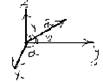 α=<(Ox. ); β=<(Oy ); γ=<(Oz, .
It is clear that the coordinates of a vector are equal to the magnitudes of the projections of this vector on the coordinate axes. Therefore X= = |cosα; Y= = |cosβ; Z= = |cosγ.
From here we can find direction cosines: cos = = ; cosβ= ; cosγ=