If you bring the magnetic needle close, it will tend to become perpendicular to the plane passing through the axis of the conductor and the center of rotation of the needle. This indicates that special forces act on the arrow, which are called magnetic forces. In addition to the effect on the magnetic needle, the magnetic field affects moving charged particles and current-carrying conductors located in the magnetic field. In conductors moving in a magnetic field, or in stationary conductors located in an alternating magnetic field, an inductive electromotive force (emf) arises.
A magnetic field
In accordance with the above, we can give the following definition of a magnetic field.
A magnetic field is one of the two sides of the electromagnetic field, excited by the electric charges of moving particles and changes in the electric field and characterized by a force effect on moving infected particles, and therefore on electric currents.
If you pass a thick conductor through cardboard and pass an electric current through it, then the steel filings poured onto the cardboard will be located around the conductor in concentric circles, which in this case are the so-called magnetic induction lines (Figure 1). We can move the cardboard up or down the conductor, but the location of the steel filings will not change. Consequently, a magnetic field arises around the conductor along its entire length.
If you put small magnetic arrows on the cardboard, then by changing the direction of the current in the conductor, you can see that the magnetic arrows will rotate (Figure 2). This shows that the direction of magnetic induction lines changes with the direction of current in the conductor.
Magnetic induction lines around a current-carrying conductor have the following properties: 1) magnetic induction lines of a straight conductor have the shape of concentric circles; 2) the closer to the conductor, the denser the magnetic induction lines are located; 3) magnetic induction (field intensity) depends on the magnitude of the current in the conductor; 4) the direction of magnetic induction lines depends on the direction of the current in the conductor.
To show the direction of the current in the conductor shown in section, a symbol has been adopted, which we will use in the future. If you mentally place an arrow in the conductor in the direction of the current (Figure 3), then in the conductor in which the current is directed away from us, we will see the tail of the arrow’s feathers (a cross); if the current is directed towards us, we will see the tip of an arrow (point).

Figure 3. Symbol for the direction of current in conductors
The gimlet rule allows you to determine the direction of magnetic induction lines around a current-carrying conductor. If a gimlet (corkscrew) with a right-hand thread moves forward in the direction of the current, then the direction of rotation of the handle will coincide with the direction of the magnetic induction lines around the conductor (Figure 4).
A magnetic needle introduced into the magnetic field of a current-carrying conductor is located along the magnetic induction lines. Therefore, to determine its location, you can also use the “gimlet rule” (Figure 5). The magnetic field is one of the most important manifestations of electric current and cannot be obtained independently and separately from the current.
  |  |
| Figure 4. Determining the direction of magnetic induction lines around a current-carrying conductor using the “gimlet rule” | Figure 5. Determining the direction of deviation of a magnetic needle brought to a conductor with current, according to the “gimlet rule” |
Magnetic induction
A magnetic field is characterized by a magnetic induction vector, which therefore has a certain magnitude and a certain direction in space.
A quantitative expression for magnetic induction as a result of generalization of experimental data was established by Biot and Savart (Figure 6). Measuring the magnetic fields of electric currents of various sizes and shapes by the deflection of the magnetic needle, both scientists came to the conclusion that every current element creates a magnetic field at some distance from itself, the magnetic induction of which is Δ B is directly proportional to the length Δ l this element, the magnitude of the flowing current I, the sine of the angle α between the direction of the current and the radius vector connecting the field point of interest to us with a given current element, and is inversely proportional to the square of the length of this radius vector r:
![]()
![]()
Where K– coefficient depending on the magnetic properties of the medium and on the chosen system of units.
In the absolute practical rationalized system of units of ICSA
where µ 0 – magnetic permeability of vacuum or magnetic constant in the MCSA system:
µ 0 = 4 × π × 10 -7 (henry/meter);
Henry (gn) – unit of inductance; 1 gn = 1 ohm × sec.
µ – relative magnetic permeability– a dimensionless coefficient showing how many times the magnetic permeability of a given material is greater than the magnetic permeability of vacuum.
The dimension of magnetic induction can be found using the formula
Volt-second is also called Weber (wb):
In practice, there is a smaller unit of magnetic induction - gauss (gs):
Biot-Savart's law allows us to calculate the magnetic induction of an infinitely long straight conductor:
![]()
![]()
Where A– the distance from the conductor to the point where the magnetic induction is determined.
Magnetic field strength
The ratio of magnetic induction to the product of magnetic permeabilities µ × µ 0 is called magnetic field strength and is designated by the letter H:
B = H × µ × µ 0 .
The last equation relates two magnetic quantities: induction and magnetic field strength.
Let's find the dimension H:
Sometimes another unit of measurement of magnetic field strength is used - Oersted (er):
1 er = 79,6 A/m ≈ 80 A/m ≈ 0,8 A/cm .
Magnetic field strength H, like magnetic induction B, is a vector quantity.
A line tangent to each point of which coincides with the direction of the magnetic induction vector is called magnetic induction line or magnetic induction line.
Magnetic flux
The product of magnetic induction by the area perpendicular to the field direction (magnetic induction vector) is called flux of the magnetic induction vector or simply magnetic flux and is denoted by the letter F:
F = B × S .
Magnetic flux dimension:
that is, magnetic flux is measured in volt-seconds or webers.
The smaller unit of magnetic flux is Maxwell (mks):
1 wb = 108 mks.
1mks = 1 gs× 1 cm 2.
Video 1. Ampere's hypothesis
Video 1. Ampere's hypothesis
Video 2. Magnetism and electromagnetism
 You can show how to use Ampere's law by determining the magnetic field near a wire. Let's ask the question: what is the field outside a long straight wire of cylindrical cross-section? We will make one assumption, perhaps not so obvious, but nevertheless correct: the field lines B go around the wire in a circle. If we make this assumption, then Ampere's law [equation (13.16)] tells us what the magnitude of the field is. Due to the symmetry of the problem, field B has the same value at all points of the circle concentric with the wire (Fig. 13.7). Then we can easily take the line integral of B·ds. It is simply equal to the value of B multiplied by the circumference. If the radius of the circle is r, That
The total current through the loop is simply the current / in the wire, so
The magnetic field strength decreases in inverse proportion to r, distance from the wire axis. If desired, equation (13.17) can be written in vector form. Recalling that B is directed perpendicular to both I and r, we have
We highlighted the factor 1/4πε 0 with 2 because it appears frequently. It is worth remembering that it is exactly 10 - 7 (in SI units), because an equation of the form (13.17) is used to definitions units of current, ampere. At a distance of 1 m a current of 1 A creates a magnetic field equal to 2 10 - 7 weber/m2.
Since the current creates a magnetic field, it will act with some force on the adjacent wire through which the current also passes. In ch. 1 we described a simple experiment showing the forces between two wires through which current flows. If the wires are parallel, then each of them is perpendicular to the B field of the other wire; then the wires will repel or attract each other. When currents flow in one direction, the wires attract; when currents flow in opposite directions, they repel.
 Let's take another example, which can also be analyzed using Ampere's law, if we also add some information about the nature of the field. Let there be a long wire coiled into a tight spiral, the cross-section of which is shown in Fig. 13.8. This spiral is called solenoid. We observe experimentally that when the length of the solenoid is very large compared to the diameter, the field outside it is very small compared to the field inside. Using only this fact and Ampere's law, one can find the magnitude of the field inside.
Since the field remains inside (and has zero divergence), its lines should run parallel to the axis, as shown in Fig. 13.8. If this is the case, then we can use Ampere's law for the rectangular "curve" G in the figure. This curve travels a distance L
inside the solenoid, where the field is, say, equal to B o, then goes at right angles to the field and returns back along the outer region, where the field can be neglected. The line integral of B along this curve is exactly At 0 L, and this must equal 1/ε 0 c 2 times the total current inside G, i.e. NI(where N is the number of solenoid turns along the length L).
We have
Or by entering n- number of turns per unit length solenoid (so n=
N/L),
we get
 What happens to the B lines when they reach the end of the solenoid? Apparently, they somehow diverge and return to the solenoid from the other end (Fig. 13.9). Exactly the same field is observed outside a magnetic rod. well and what is it magnet? Our equations say that field B arises from the presence of currents. And we know that ordinary iron bars (not batteries or generators) also create magnetic fields. You might expect that there would be other terms on the right-hand side of (13.12) or (16.13) representing the "density of magnetized iron" or some similar quantity. But there is no such member. Our theory says that the magnetic effects of iron arise from some internal currents already taken into account by the j term.
Matter is very complex when viewed from a deep point of view; We were already convinced of this when we tried to understand dielectrics. In order not to interrupt our presentation, we will postpone a detailed discussion of the internal mechanism of magnetic materials such as iron. For now we will have to accept that any magnetism arises due to currents and that there are constant internal currents in a permanent magnet. In the case of iron, these currents are created by electrons rotating around their own axes. Each electron has a spin that corresponds to a tiny circulating current. One electron, of course, does not produce a large magnetic field, but an ordinary piece of matter contains billions and billions of electrons. Usually they rotate in any way so that the net effect disappears. The surprising thing is that in a few substances like iron, most of the electrons rotate around axes directed in one direction - in iron, two electrons from each atom take part in this joint movement. A magnet contains a large number of electrons spinning in the same direction, and, as we will see, their net effect is equivalent to the current circulating across the surface of the magnet. (This is very similar to what we find in dielectrics—a uniformly polarized dielectric is equivalent to the distribution of charges on its surface.) It is therefore no coincidence that a bar magnet is equivalent to a solenoid.
Let's consider a straight conductor (Fig. 3.2), which is part of a closed electrical circuit. According to the Biot-Savart-Laplace law, the magnetic induction vector  field created at a point A element
  current carrying conductor I,
has the meaning
current carrying conductor I,
has the meaning  , Where
  - angle between vectors
  And
And  . For all areas
  this conductor vectors
  And
And  lie in the plane of the drawing, therefore at the point A all vectors
  , created by each section
  , directed perpendicular to the plane of the drawing (towards us). Vector
  determined by the principle of field superposition:
 ,
,
its modulus is:
 .
.
Let us denote the distance from the point A to the conductor  . Consider a conductor section
  . From point A let's draw an arc WITHD radius
  ,
, – small, therefore
  And
And  . From the drawing it is clear that
  ;
; , But
, But  (CD=
(CD= ) Therefore we have:
 .
.
For  we get:
Where  And
And  - angle values for the extreme points of the conductor MN.
If the conductor is infinitely long, then  ,
, . Then

the induction at each point of the magnetic field of an infinitely long straight conductor with current is inversely proportional to the shortest distance from this point to the conductor.
3.4. Magnetic field of circular current
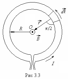 Consider a circular turn of radius R, through which current flows I
(Fig. 3.3) .
According to the Biot-Savart-Laplace law, induction
Consider a circular turn of radius R, through which current flows I
(Fig. 3.3) .
According to the Biot-Savart-Laplace law, induction  field created at a point ABOUT element
  turn with current is equal to:
 ,
,
and  , That's why
  , And
, And  . Taking this into account, we get:
 .
.
All vectors  directed perpendicular to the drawing plane towards us, therefore induction
tension  .
.
Let S– area covered by a circular turn,  . Then the magnetic induction at an arbitrary point on the axis of a circular coil with current:
 ,
,
Where  – distance from the point to the surface of the coil. It is known that
  - magnetic moment of the turn. Its direction coincides with the vector
  at any point on the axis of the coil, therefore
  , And
, And  .
.
Expression for  similar in appearance to the expression for the electric displacement at field points lying on the axis of the electric dipole sufficiently far from it:
 .
.
Therefore, the magnetic field of the ring current is often considered as the magnetic field of some conventional “magnetic dipole”; the positive (north) pole is considered to be the side of the plane of the coil from which the magnetic field lines exit, and the negative (south) pole is the one into which they enter.
For a current loop of arbitrary shape:
 ,
,
Where  - unit vector of outer normal to the element
  surfaces S,
limited by a contour. In the case of a flat contour, the surface S
– flat and all vectors
surfaces S,
limited by a contour. In the case of a flat contour, the surface S
– flat and all vectors  match up.
3.5. Solenoid magnetic field
A solenoid is a cylindrical coil with a large number of turns of wire. The solenoid turns form a helical line. If the turns are located closely, then the solenoid can be considered as a system of series-connected circular currents. These turns (currents) have the same radius and a common axis (Fig. 3.4).
Let's consider the cross section of the solenoid along its axis. We will use circles with a dot to denote currents coming from behind the drawing plane towards us, and a circle with a cross will denote currents coming beyond the drawing plane, away from us. L– solenoid length, n
–
number of turns per unit length of the solenoid; -
R- radius of the turn. Consider the point A, lying on the axis  solenoid. It is clear that magnetic induction
  at this point is directed along the axis
  and is equal to the algebraic sum of the inductions of magnetic fields created at this point by all turns.
Let's draw from the point A radius – vector  to any turn. This radius vector forms with the axis
  corner α
. The current flowing through this turn creates at the point A magnetic field with induction
corner α
. The current flowing through this turn creates at the point A magnetic field with induction 
 .
.
Let's consider a small area  solenoid, it has
  turns. These turns are created at a point A magnetic field, the induction of which
 .
.
It is clear that the axial distance from the point A to the site  equals
  ; Then
  .Obviously,
  , Then
Magnetic induction of fields created by all turns at a point A equal to
Magnetic field strength at a point A
 .
.
From Fig.3. 4 we find:  ;
; .
.
Thus, magnetic induction depends on the position of the point A on the solenoid axis. She
maximum in the middle of the solenoid:
 .
.
If L>>
R, then the solenoid can be considered infinitely long, in this case  ,
, ,
, ,
, ; Then
 ;
;
 .
.
At one end of the long solenoid  ,
, or
or  ;
; ,
, ,
, .
.
Magnetic field of a current-carrying conductor. When current passes through a straight conductor, a magnetic field appears around it (Fig. 38). The magnetic lines of force of this field are located in concentric circles, in the center of which there is a current-carrying conductor.
The direction of the magnetic field around a current-carrying conductor is always in strict accordance with the direction of the current passing through the conductor. The direction of magnetic field lines can be determined using the gimlet rule. It is formulated as follows. If the translational movement of the gimlet 1 (Fig. 39, a) is combined with the direction of the current 2 in the conductor 3, then the rotation of its handle will indicate the direction of the magnetic field lines 4 around the conductor. For example, if a current passes through a conductor in a direction away from us beyond the plane of a book sheet (Fig. 39, b), then the magnetic field that arises around this conductor is directed clockwise. If the current through the conductor passes in the direction from the plane of the book sheet towards us, then the magnetic field around the conductor is directed counterclockwise. The greater the current passing through the conductor, the stronger the magnetic field that arises around it. When the direction of the current changes, the magnetic field also changes its direction.
As you move away from the conductor, the magnetic field lines are less frequent. Consequently, the magnetic field induction and its strength decrease. The magnetic field strength in the space surrounding the conductor is
H = I/(2?r) (44)
The maximum tension H max occurs on the outer surface of conductor 1 (Fig. 40). Inside the conductor also

a magnetic field arises, but its intensity decreases linearly in the direction from the outer surface to the axis (curve 2). The magnetic induction of the field around and inside the conductor changes in the same way as the voltage.
Methods of strengthening magnetic fields. To obtain strong magnetic fields at low currents, they usually increase the number of current-carrying conductors and make them in the form of a series of turns; such a device is called a winding or coil.
With a conductor bent in the form of a coil (Fig. 41, a), the magnetic fields formed by all sections of this conductor will have the same direction inside the coil. Therefore, the intensity of the magnetic field inside the coil will be greater than around a straight conductor. When the turns are combined into a coil, the magnetic fields created by the individual turns add up (Fig. 41, b) and their lines of force are connected into a common magnetic flux. In this case, the concentration of field lines inside the coil increases, i.e., the magnetic field inside it intensifies. The greater the current passing through the coil, and the more turns there are in it, the stronger the magnetic field created by the coil. The magnetic field outside the coil also consists of the magnetic fields of individual turns, but the magnetic field lines are not so densely located, as a result of which the intensity of the magnetic field there is not as great as inside the coil. The magnetic field of a coil flowing around current has the same shape as the field of a rectilinear permanent magnet (see Fig. 35, a): magnetic lines of force come out of one end of the coil and enter its other end. Therefore, a coil flowing around a current is an artificial electric magnet. Typically, a steel core is inserted inside the coil to enhance the magnetic field; such a device is called an electromagnet.
Electromagnets have found extremely wide application in technology. They create the magnetic field necessary for the operation of electrical machines, as well as the electrodynamic forces required. For operation of various electrical measuring instruments and electrical devices.
Electromagnets can have an open or closed magnetic circuit (Fig. 42). The polarity of the end of the electromagnet coil can be determined, like the polarity of a permanent magnet, using a magnetic needle. It turns towards the North Pole with its southern end. To determine the direction of the magnetic field created by a turn or coil, you can also use the gimlet rule. If you combine the direction of rotation of the handle with the direction of the current in the coil or coil, then the forward movement of the gimlet will indicate the direction of the magnetic field. The polarity of the electromagnet can also be determined using the right hand. To do this, you need to place your hand on the coil (Fig. 43) and align four fingers with the direction of the current in it, while the bent thumb will show the direction of the magnetic field.
If you bring a magnetic needle to a straight conductor carrying an electric current, it will tend to become perpendicular to the plane passing through the axis of the conductor and the center of rotation of the needle. This indicates that the needle is subject to special forces called magnetic forces. In addition to the effect on the magnetic needle, the magnetic field affects moving charged particles and current-carrying conductors located in the magnetic field. In conductors moving in a magnetic field, or in stationary conductors located in an alternating magnetic field, an inductive emission occurs. d.s.
|

In accordance with the above, we can give the following definition of a magnetic field.
A magnetic field is one of the two sides of an electromagnetic field, excited by electric charges of moving particles and changes in the electric field and characterized by a force effect on moving charged particles, and therefore on electric currents.
If you pass a thick conductor through cardboard and pass an electric current through it, then the steel filings poured onto the cardboard will be located around the conductor in concentric circles, which in this case are the so-called magnetic induction lines (Fig. 78). We can move the cardboard up or down the conductor, but the location of the steel filings will not change. Consequently, a magnetic field arises around the conductor along its entire length.
If you place small magnetic arrows on the cardboard, then by changing the direction of the current in the conductor, you can see that the magnetic arrows will rotate (Fig. 79). This shows that the direction of magnetic induction lines changes with the direction of current in the conductor.
Magnetic induction lines around a current-carrying conductor have the following properties: 1) magnetic induction lines of a straight conductor have the shape of concentric circles; 2) the closer to the conductor, the denser the magnetic induction lines are located; 3) magnetic induction (field intensity) depends on the magnitude of the current in the conductor; 4) the direction of magnetic induction lines depends on the direction of the current in the conductor.
|

The direction of magnetic induction lines around a current-carrying conductor can be determined by the “gimlet rule:”. If a gimlet (corkscrew) with a right-hand thread moves translationally in the direction of the current, then the direction of rotation of the handle will coincide with the direction of the magnetic induction lines around the conductor (Fig. 81),
A magnetic needle introduced into the field of a current-carrying conductor is located along the magnetic induction lines. Therefore, to determine its location, you can also use the “gimlet rule” (Fig. 82). The magnetic field is one of the most important manifestations of electric current and cannot be
Obtained independently and separately from current. A magnetic field is characterized by a magnetic induction vector, which therefore has a certain magnitude and a certain direction in space.
|

A quantitative expression for magnetic induction as a result of a generalization of experimental data was established by Biot and Savart (Fig. 83). Measuring the magnetic fields of electric currents of various sizes and shapes by the deflection of the magnetic needle, both scientists came to the conclusion that every current element creates a magnetic field at some distance from itself, the magnetic induction AB of which is directly proportional to the length A1 of this element, the magnitude of the flowing current I, sine angle a between the direction of the current and the radius vector connecting the field point of interest to us with a given current element, and is inversely proportional to the square of the length of this radius vector r:
henry (h) is a unit of inductance; 1 gn = 1 ohm sec.
- relative magnetic permeability - a dimensionless coefficient showing how many times the magnetic permeability of a given material is greater than the magnetic permeability of the void. The dimension of magnetic induction can be found using the formula
Volt-second is otherwise called Weber (vb):
|
In practice, there is a smaller unit of magnetic induction - gauss (gs):
![]()
Biot and Savart's law allows us to calculate the magnetic induction of an infinitely long straight conductor:
![]()
where is the distance from the conductor to the point where it is determined
Magnetic induction. The ratio of magnetic induction to the product of magnetic permeabilities is called magnetic field strength and is denoted by the letter H:

The last equation relates two magnetic quantities: induction and magnetic field strength. Let's find the dimension H:
![]()
Sometimes they use another unit of tension - the oersted (er):
1 er = 79.6 a/m = 0.796 a/cm.
The magnetic field strength H, like the magnetic induction B, is a vector quantity.
A line tangent to each point of which coincides with the direction of the magnetic induction vector is called a magnetic induction line or magnetic induction line.
The product of magnetic induction and the magnitude of the area perpendicular to the direction of the field (magnetic induction vector) is called the flux of the magnetic induction vector or simply magnetic flux and is denoted by the letter F:
Magnetic flux dimension:
i.e., magnetic flux is measured in volt-seconds or webers. A smaller unit of magnetic flux is the maxwell (µs):
1 wb = 108 µs. 1 μs = 1 gf cm2.